(4/2024) FlipFlop Clock
This is my project creating a clock. The clock is implemented using a PCB. (Printed Circuit Board) This project uses Kicad and demonstrates understanding of flipflops, counters, and the circuitry design process.
Abstract Link to heading
This is a guided project done in collaboration with IEEE. The main goal of this project is to reinforce my understanding of flipflops and counters.
Design Link to heading
Goal The goal of the ornament is to make a functional 24 hour clock. To achieve this, the PCB is designed to display four numbers through four seven segment displays, representing the hours and minutes of the current time. There will be two buttons to increment the hour and minute count respectively to be able to set the time manually.
We can verify this through blinking LEDs placed between the hours and the minutes. They should blink at a 1Hz frequency, verifying that our signal for tracking time is operating correctly.
Implementation
Time Tracking the time requires a signal at a consistent frequency. To achieve this I used a crystal oscillator specifically, a common place 32.768 kHz crystal. This signal is then treated through the 4060 IC chip to produce a 1Hz signal. One thing to note here is that the crystal oscillator operated under 3.3V logic, while the chip operated with 5V. This meant that a stage amp was needed to trasform the signal from 3.3V to 5V.
Reset Once the signal is established, it can be fed into a counter. The board is wired such that every one second, the counter counts up by one.
In order to implement reset behavior and have a functional minute and hour counters. A counter for seconds is first implemented, which will increment by one every second through the 1Hz signal. A minute counter is implemented which increases by one every time the second counter hits sixty. At which point the second counter is reset. Once the minute counter hits sixty, the hour counter increments by one and the minute counter resets. The hour counter then resets once it hits twenty four.
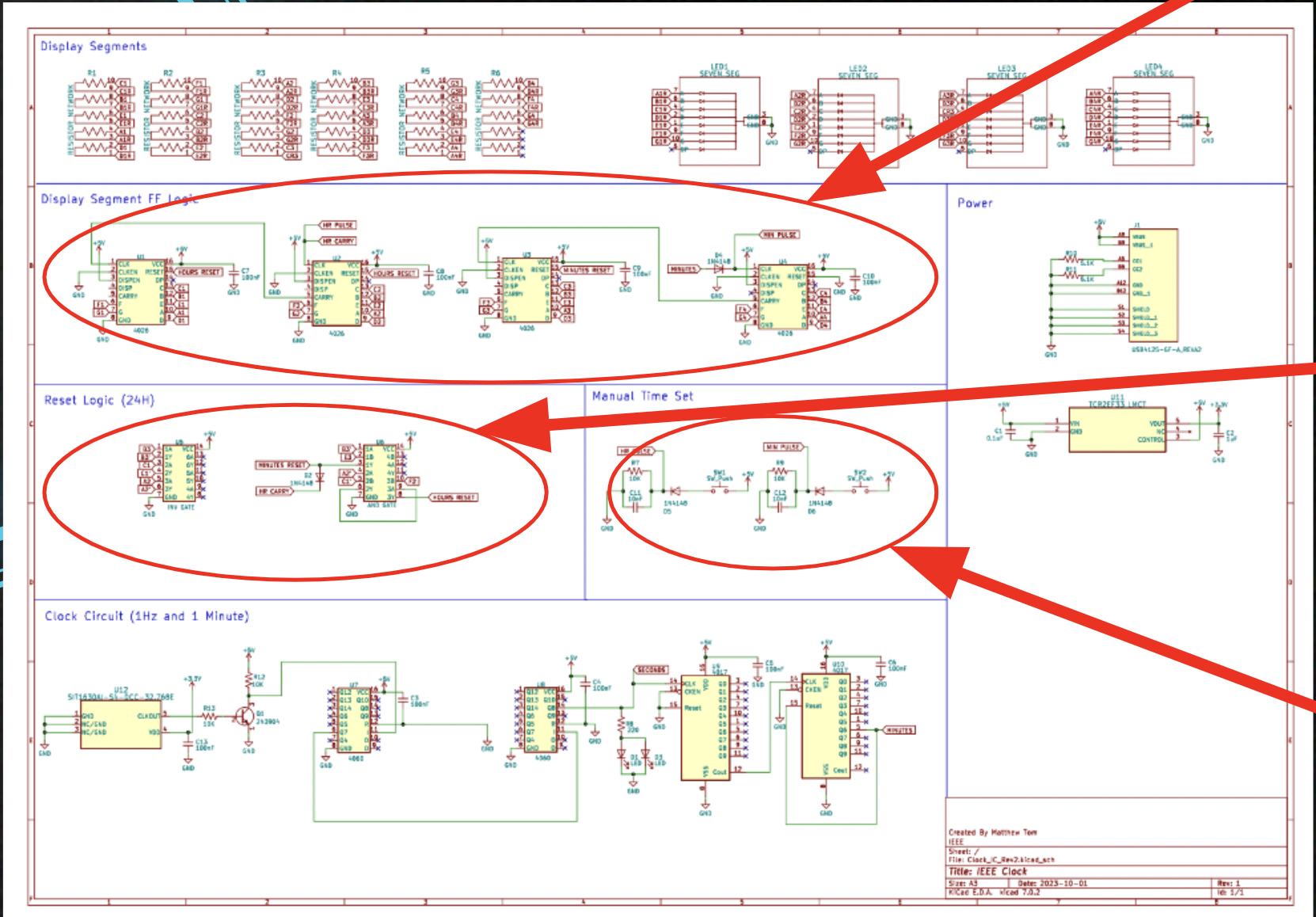
This entire process is be implemented with logic through the 4026 chips. The schematics and wiring is provided below.
Inputs The inputs to the circuit will only be two buttons. The hour button and the minute button. The hour button will increment the hour by one and the minute will increment the minute by one. This will be how the user sets the time.
Buttons face issues such as debouncing, which I have solved through implementing an RC circuit to clean the signal.
Materials PCB board USB-C cable 6 resistor networks 6 Capacitors 2 LEDs 4 Diodes 2 CD4060BE chips 2 CD4017BE chips SN74LS04N chip SN74LS08N chip 4 CD4026BE chips MEMS Oscillator circuit set (crystal clock) 2 buttons 4 seven segment displays 1 transistor USB-C port (to solder onto the board)
Tools Link to heading
All materials were provided by IEEE and assembled by me through soldering.
KiCad design Link to heading
The specifics of the circuit logic is found here in the schematics:

Demo Link to heading
Future improvements and conclusion Link to heading
As the demo showcases, there are several shortcomings of the finished project that I would improve if I were to remake the clock.
The first issue is the LEDs in the center are not blinking. In the design, the LEDs are supposed to blink at a 1Hz frequency, but they are not lit up in the demo. This is due to a poor soldering job on my part, as I messed up the tracing’s connection trying to fix another soldering mistake that I had made. This can be simply fixed with greater caution and skill in soldering.
The second issue is that many of the exposed parts of the PCB can cause shorts which can cause undefined behavior, such as the counter incrementing as fast as the capacitor would allow instead of following the 1Hz signal. This is demonstrated at the end of the demo, where I touch an exposed diode, causing the counters to count up rapidly. This can be fixed by making casings and covers for the exposed parts of the circuit. Alternatively, it may be easier to simply make all parts into surface mounts to reduce the chance of something touching it and shorting the circuit, though this will make soldering much more difficult.
Ultimately, the clock functions and behaves as expected overall, and I am happy with how the PCB turned out.